


142 www.xilinx.com Development System Reference Guide
Chapter 7: MAP
R
4. Removes unused logic. All unused components and nets are removed, unless the
following conditions exist:
♦ A Xilinx S (Save) constraint has been placed on a net during design entry. If an
unused net has an S constraint, the net and all used logic connected to the net (as
drivers or loads) is retained. All unused logic connected to the net is deleted.
For a more complete description of the S constraint, see the Constraints Guide.
♦ The –u option was specified on the MAP command line. If this option is specified,
all unused logic is kept in the design.
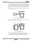
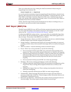
5. Maps pads and their associated logic into IOBs.
6. Maps the logic into Xilinx components (IOBs, CLBs, etc.). If any Xilinx mapping
control symbols appear in the design hierarchy of the input file (for example, FMAP
symbols targeted to a Xilinx device), MAP uses the existing mapping of these
components in preference to remapping them. The mapping is influenced by various
constraints; these constraints are described in the Constraints Guide.
7. Update the information received from the input NGD file and write this updated
information into an NGM file. This NGM file contains both logical information about
the design and physical information about how the design was mapped. The NGM file
is used only for back-annotation. On Virtex/-E/-II devices, guided mapping uses the
NGM file. For more information, see “Guided Mapping”.
8. Create a physical constraints (PCF) file. This is a text file that contains any constraints
specified during design entry. If no constraints were specified during design entry, an
empty file is created so that you can enter constraints directly into the file using a text
editor or indirectly through the FPGA Editor.
MAP either creates a PCF file if none exists or rewrites an existing file by overwriting
the schematic-generated section of the file (between the statements SCHEMATIC
START and SCHEMATIC END). For an existing constraints file, MAP also checks the
user-generated section and may either comment out constraints with errors or halt the
program. If no errors are found in the user-generated section, the section remains the
same.
Note:
For Virtex/-E/-II/-II PRO designs, you must use a MAP generated PCF file. The timing
tools perform skew checking only with a MAP-generated PCF file.
9. Run a physical Design Rule Check (DRC) on the mapped design. If DRC errors are
found, MAP does not write an NCD file.
10. Create an NCD file, which represents the physical design. The NCD file describes the
design in terms of Xilinx components—CLBs, IOBs, etc.
11. Write a MAP report (MRP) file, which lists any errors or warnings found in the design,
details how the design was mapped, and supplies statistics about component usage in
the mapped design.
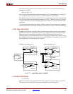
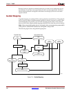
Register Ordering
When you run MAP, the default setting performs register ordering. If you specify the –r
option, MAP does not perform register ordering and maps the register bits as if they were
unrelated.
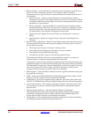
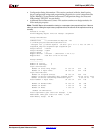
When you map a design containing registers, the MAP software can optimize the way the
registers are grouped into CLBs (slices for Virtex/-E/-II/-II PRO or Spartan-II/-IIE —
there are two slices per CLB). This optimized mapping is called register ordering.