


320 www.xilinx.com Development System Reference Guide
Chapter 22: NetGen
R
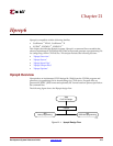
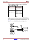
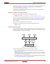
The Functional Simulation flow uses the following files as input:
• NGC —This file output by XST is used to create a UNISIM-based netlist suitable for
using with IP Cores and performing post-synthesis functional simulation.
• NGD—This file output by NGDBuild contains a logical description of the design and
is used to create a SIMPRIM-based netlist.
Notes on Functional Simulation for UNISIM-based Netlists
For XST users, the output NGC file can be entered on the command line. For third-party
synthesis tool users, you must first use the ngcbuild command to convert all of the design
netlists to a single NGC file, which NetGen takes as input.
The following command reads the top-level EDIF netlist and converts it to an NGC file:
ngcbuild
[options] top_level_netlist_file output_ngc_file
Note:
For information on NGCBuild, see Answer Record #21851 at http://www.xilinx.com/support.
Syntax for NetGen Functional Simulation
The following command runs the NetGen Functional Simulation flow:
netgen -ofmt {verilog|vhdl} [options] input_file[.ngd|ngc|ngo]
verilog or vhdl is the output netlist format that you specify with the required –ofmt option.
options is one or more of the options listed in the “Options for NetGen Simulation Flow”
section. In addition to common options, this section also contains Verilog and VHDL-
specific options.
input_file is the input file name and extension.
Output files for NetGen Functional Simulation
• V file—This is a IEEE 1364-2001 compliant Verilog HDL file that contains the netlist
information obtained from the input design files. This file is a functional simulation
model and cannot be synthesized or used in any manner other than simulation.
• VHD file—This VHDL IEEE 1076.4 VITAL-2000 compliant VHDL file contains the
netlist information obtained from the input design files. This file is a simulation model
and cannot be synthesized or used in any other manner than simulation.
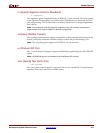
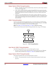
NetGen Timing Simulation Flow
This section describes the NetGen Timing Simulation flow, which is used for timing
verification on FPGA and CPLD designs. For FPGA designs, timing simulation is done
after PAR, but may also be done after MAP if only component delay and no route delay
information is needed. When performing timing simulation, you must specify the type of
netlist you want to create: Verilog or VHDL. In addition to the specified netlist, NetGen
also creates an SDF file as output. The output Verilog and VHDL netlists contain the
functionality of the design and the SDF file contains the timing information for the design.