


Development System Reference Guide www.xilinx.com 133
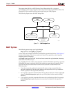
MAP Options
R
–bp (Map Slice Logic)
The block RAM mapping option is enabled when the –bp option is specified. When block
RAM mapping is enabled, MAP attempts to place LUTs and FFs into single-output, single-
port block RAMs.
You can create a file containing a list of register output nets that you want converted into
block RAM outputs. To instruct MAP to use this file, set the environment variable
XIL_MAP_BRAM_FILE to the file name. MAP looks for this environment variable when
the –bp option is specified. Only those output nets listed in the file are made into block
RAM outputs.
Note:
Because block RAM outputs are synchronous and can only be reset, the registers packed
into a block RAM must also be synchronous reset.
–c (Pack CLBs)
–c [packfactor]
The –c option determines the degree to which CLBs are packed when the design is
mapped. The valid range of values for the packfactor is 0–100.
The packfactor values ranging from 1 to 100 roughly specify the percentage of CLBs
available in a target device for packing your design's logic.
A packfactor of 100 means that all CLBs in a target part are available for design logic. A
packfactor of 100 results in minimum packing density, while a packfactor of 1 represents
maximum packing density. Specifying a lower packfactor results in a denser design, but the
design may then be more difficult to place and route.
The –c 0 option specifies that only related logic (that is, logic having signals in common)
should be packed into a single CLB. Specifying –c 0 yields the least densely packed design.
For values of –c from 1 to 100, MAP merges unrelated logic into the same CLB only if the
design requires more resources than are available in the target device (an overmapped
design). If there are more resources available in the target device than are needed by your
design, the number of CLBs utilized when –c 100 is specified may equal the number
required when –c 0 is specified.
Note:
The –c 1 setting should only be used to determine the maximum density (minimum area) to
which a design can be packed. Xilinx does not recommend using this option in the actual
implementation of your design. Designs packed to this maximum density generally have longer run
times, severe routing congestion problems in PAR, and poor design performance.
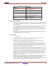
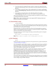
–retiming Virtex-4 architectures
–t All FPGA architectures
–timing All FPGA architectures
–tx Not used for Virtex-4, Spartan-3, Spartan-
3E, or Spartan-3L architectures
–u All FPGA architectures
–xe All FPGA architectures
Table 7-1: Map Options and Architectures
Options Architectures