


Development System Reference Guide www.xilinx.com 321
NetGen Timing Simulation Flow
R
Input file types depend on whether you are using an FPGA or CPLD design. Please refer to
“FPGA Timing Simulation” and “CPLD Timing Simulation” for design-specific
information, including input file types.
A complete list of command line options for performing NetGen Timing Simulation
appears at the end of this section.
Syntax for NetGen Timing Simulation
The following command runs the NetGen Timing Simulation flow:
netgen -sim -ofmt {verilog|vhdl} [options] input_file[.ncd]
verilog or vhdl is the output netlist format that you specify with the required –ofmt option.
options is one or more of the options listed in the “Options for NetGen Simulation Flow”
section. In addition to common options, this section also contains Verilog and VHDL-
specific options.
input_file is the input NCD file name and extension.
To get help on command line usage for NetGen Timing Simulation, type:
netgen -h sim
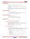
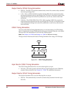
FPGA Timing Simulation
You can verify the timing of an FPGA design using the NetGen Timing Simulation flow to
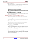
generate a Verilog or VHDL netlist and an SDF file. The figure below illustrates the NetGen
Timing Simulation flow using an FPGA design.
The FPGA Timing Simulation flow uses the following files as input:
• NCD —This physical design file may be mapped only, partially or fully placed, or
partially or fully routed.
• PCF (optional)—This is a physical constraints file. If prorated voltage or temperature
is applied to the design, the PCF must be included to pass this information to NetGen.
See “–pcf (PCF File)” for more information.
• ELF (MEM) (optional)—This file populates the Block RAMs specified in the .bmm file.
See “–bd (Block RAM Data File)” for more information.
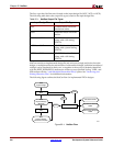
Figure 22-2: FPGA Timing Simulation
X10250
NetGen
PCF
SDF
ELFNCD
Simulation Tool
Simprim
Library
V/VHD