


44 www.xilinx.com Development System Reference Guide
Chapter 2: Design Flow
R
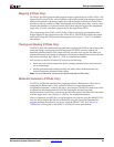
NetGen
NetGen is a command line program that distributes information about delays, setup and
hold times, clock to out, and pulse widths found in the physical NCD design file back to
the logical NGD file and generates a Verilog or VHDL netlist for use with supported
timing simulation, equivalence checking, and static timing analysis tools.
NetGen reads an NCD as input. The NCD file can be a mapped-only design, or a partially
or fully placed and routed design. An NGM file, created by MAP, is an optional source of
input. NetGen merges mapping information from the optional NGM file with placement,
routing, and timing information from the NCD file.
Note:
NetGen reads an NGA file as input to generate a timing simulation netlist for CPLD designs.
See Chapter 22, “NetGen” for detailed information.
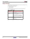
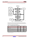
Schematic-Based Simulation
Design simulation involves testing your design using software models. It is most effective
when testing the functionality of your design and its performance under worst-case
conditions. You can easily probe internal nodes to check the behavior of your circuit, and
then use these results to make changes in your schematic.
Simulation is performed using third-party tools that are linked to the Xilinx Development
System. Use the various CAE-specific interface user guides, which cover the commands
and features of the Xilinx-supported simulators, as your primary reference.
The software models provided for your simulation tools are designed to perform detailed
characterization of your design. You can perform functional or timing simulation, as
described in the following sections.
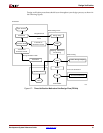
Functional Simulation
Functional simulation determines if the logic in your design is correct before you
implement it in a device. Functional simulation can take place at the earliest stages of the
design flow. Because timing information for the implemented design is not available at
this stage, the simulator tests the logic in the design using unit delays.
Note:
It is usually faster and easier to correct design errors if you perform functional simulation early
in the design flow.
You can use integrated and non-integrated simulation tools. Integrated tools, such as
Mentor Graphics or Innoveda, often contain a built-in interface that links the simulator and
a schematic editor, allowing the tools to use the same netlist. You can move directly from
entry to simulation when using a set of integrated tools.
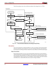
Functional simulation in schematic-based tools is performed immediately after design
entry in the capture environment. The schematic capture tool requires a Xilinx Unified
Library and the simulator requires a library if the tools are not integrated. Most of the
schematic-based tools require translation from their native database to EDIF for
implementation. The return path from implementation is usually EDIF with certain
exceptions in which a schematic tool is tied to an HDL simulator.