


140 www.xilinx.com Development System Reference Guide
Chapter 7: MAP
R
–timing (Timing-Driven Packing and Placement)
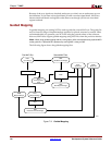
Timing-driven packing and placement is recommended to improve design performance,
timing, and packing for highly utilized designs. If the unrelated logic number (shown in
the Design Summary section of the MAP report) is non-zero, then the –timing option is
useful for packing more logic in the device. Timing-driven packing and placement is also
recommended when there are local clocks present in the design.
Note:
PAR issues a message to run timing-driven packing if it detects local clocks in the design.
The –timing option is not supported on Virtex, Virtex-E, Spartan-II, and Spartan-IIE architectures.
The –timing option directs MAP to give priority to timing critical paths during packing,
then places the design. Any user-generated timing constraints, contained in the UCF, drive
the packing and placement operations. Use of the –timing option may result in longer
runtime during the MAP process because designs are also placed; although, PAR runtime
will be reduced since the placement phase is complete.
If Timing-driven packing and placement is selected in the absence of user timing
constraints, the tools will automatically generate and dynamically adjust timing
constraints for all internal clocks. This feature is referred to as “Performance Evaluation”
mode. This mode allows the clock performance for all clocks in the design to be evaluated
in one pass. The performance achieved by this mode is not necessarily the best possible
performance each clock can achieve, instead it is a balance of performance between all
clocks in the design.
The –ol option is used in conjunction with the –timing option to set the overall effort level
that MAP uses to pack, and then place the design. See “–ol (Overall Effort Level)” for more
information.
Note:
The following options are specific to timing-driven packing and placement (–timing): –ol,
–register_duplication, –t, and –xe. See individual option descriptions in this section for details.
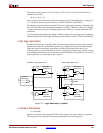
–tx (Transform Buses)
–tx {on | off | aggressive | limit}
The –tx option specifies what type of bus transformation MAP performs. The four
permitted settings are on, off, aggressive, and limit. The following example shows how the
settings are used. In this example, the design has the following characteristics and is
mapped to a Virtex device:
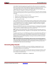
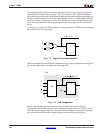
• Bus A has 4 BUFTs
• Bus B has 20 BUFTs
• Bus C has 30 BUFTs
MAP processes the design in one of the following ways, based on the setting used for the
–tx option:
• The on setting performs partial transformation for a long chain that exceeds the
device limit.
♦ Bus A is transformed to LUTs (number of BUFTs is >1, ≤4)
♦ Bus B is transformed to CY chain (number of BUFTs is >4, ≤48)
♦ Bus C is partially transformed. (25 BUFTs + 1 dummy BUFT due to the maximum
width of the XCV50 device + CY chain implementing the other 5 BUFTs)
• The off setting turns bus transformation off. This is the default setting.